Factory Service Manual For Mustang All Wheel Steer Loader. Manual Contains Illustrations, Instructions, Diagrams For Step By Step Remove And Install, Assembly And Disassembly, Service, Inspection, Repair, Troubleshooting, Tune-Ups.
Format: PDF
Language: English
Pages: 208
Issued: september 2005
Searchable: Yes
Wiring Diagrams: Yes
Hydraulic Diagrams: Yes
Model
Mustang All Wheel Steer Loader
ML48T
Contents
-OPERATION
Important Information On This Service Manual
Type Decals And Component Numbers
Machine Overview
Cab Overview
Instrument Panel, Multifunctional Lever And Drive Lever: Overview
-SPECIFICATIONS
Frame
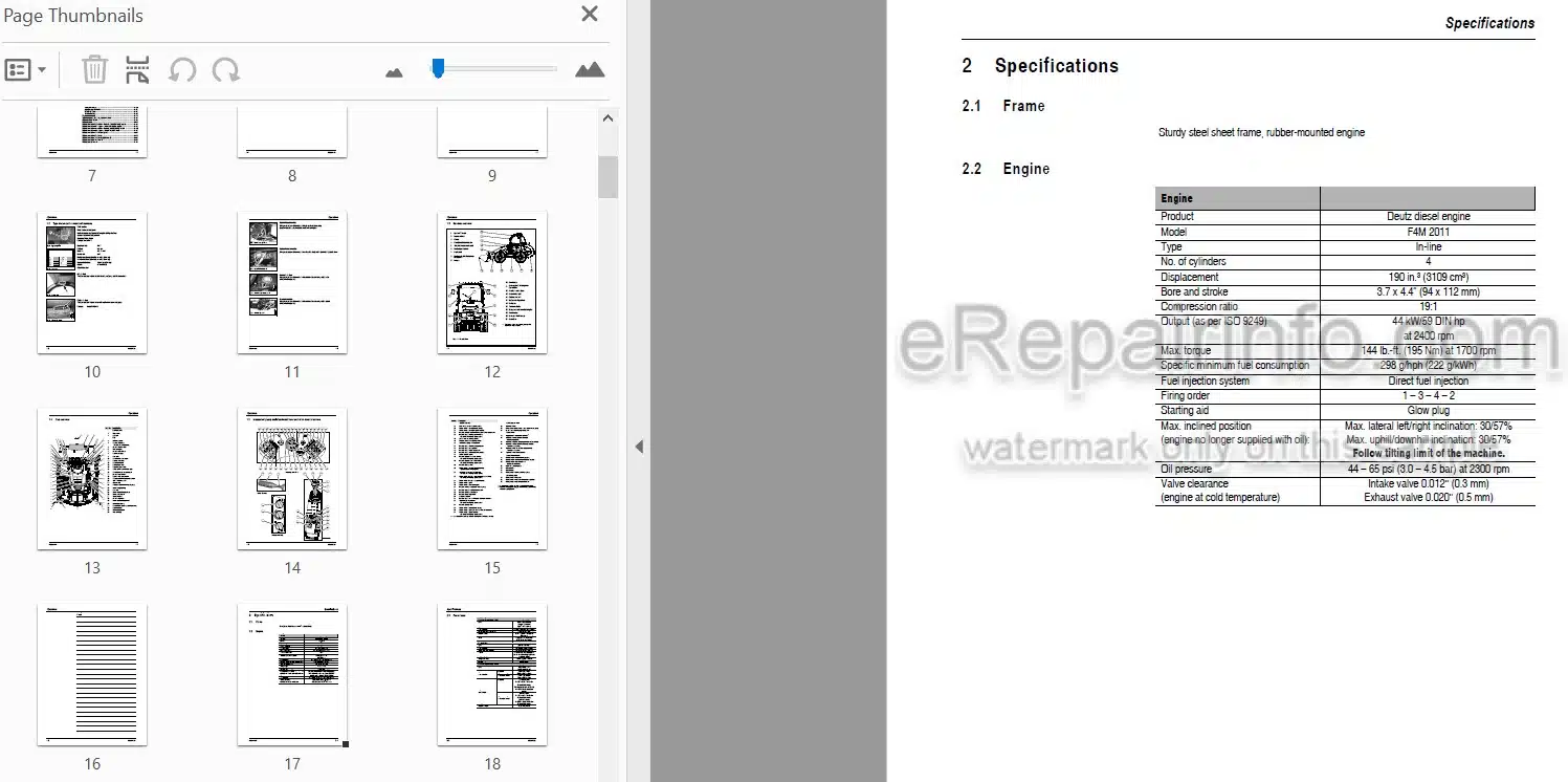
Engine
Power Train
Axles
Brakes
Steering
Work Hydraulics
Pilot Control
Loader Unit
Electrical System
Tires
Weights
Sound Levels
Vibration
Tightening Torques
-MAINTENANCE
Fluids And Lubricants
Maintenance Decal
Maintenance Schedule Model 480T (Overview)
Maintenance Items
Introduction
Fuel System
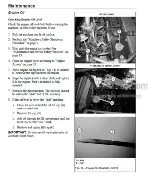
Engine Lubrication System
Engine And Hydraulic Cooling System
Air Filter
V-Belt
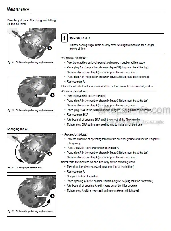
Gearboxes And Axles
Hydraulic System
Checking The Hydraulic Oil Level
Filling Up The Hydraulic Oil
Monitoring The Hydraulic Oil Return Filter
Lubrication Work
Maintenance Of Attachments
Maintenance Of The Brake System
Tire Maintenance
Changing Wheels
Electrical System
General Maintenance Work
Heating
-ENGINE
BF4M 2011/ F4M 2011 Engine: Overview
Engine Oil Cooling
Fuel System
Engine Level 2 (Tier II)
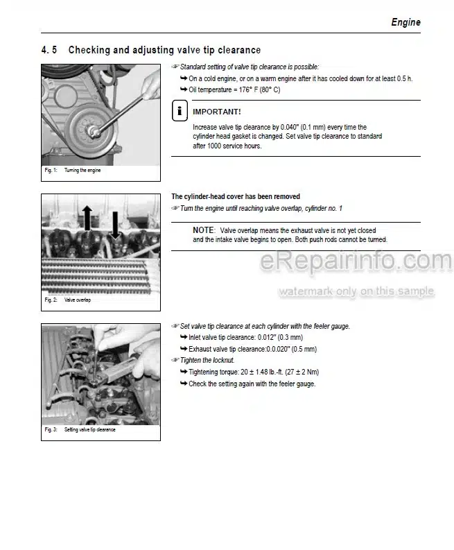
Checking And Adjusting Valve Tip Clearance
Replacing The Fuel Injection Pump
Removing/Mounting The Cylinder Head
Engine Trouble
-POWER TRAIN
Variable-Displacement Pump 125 mph (20 km/h)
Hydraulic Motor – Hydraulic Connections 125 mph (20 km/h)
Hydraulic Motor – Control Element 125 mph (20 km/h)
Power Train Circuit With Cooling 125 mph (20 km/h)
Power Train Diagram 125 mph (20 km/h)
Inching Valve (Left-Hand Side Access)
Inching Valve (Component Parts)
Test Report 125 mph (20 km/h)
Towing And Transporting The Machine
Adjustment Work On Power Train
Eco Speed 25 mph (40 km/h High Speed)
Eco Speed Power Train 25 mph (40 km/h): Diagram
25 mph (40 km/h) Test Report
Control Initiation M3: Settings
Control Initiation M4: Settings
Wheel Speed: Settings
-AXLES
Type Decal – Axle
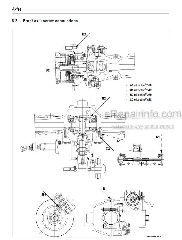
Front Axle Screw Connections
Rear Axle Screw Connections
Drain, Fill And Check Plug – Front Axle
Drain, Fill And Check Plug – Rear Axle
Tightening Torques Ib-Ft (Nm) – Front Axle
Tightening Torques Ib-Ft (Nm) – Rear Axle
Sealing Work
Differential Lock
-BRAKES
Brake Circuit
Bleeding The Service Brake
Parking Brake: Overview
-STEERING
125 mph (20 km/h) Steering Circuit
125 mph (20 km/h) Steering Diagram
25 mph (40 km/h) Steering Circuit
25 mph (40 km/h) Steering Diagram
Hydraulic Connections On Servostat
Pressure Relief Valve – Servostat: Settings
Sealing The Steering Cylinder 125 mph/25 mph (20 km/h/40 km/h)
Adjusting The Steering Sensors 25 mph (40 km/h)
-HYDRAULIC SYSTEM
Test Report
Control Valve Connections
Work Hydraulics Circuit
Connections: Frame – Loader Unit Disconnect
Loader Unit Hose Routing
Pilot Control Unit: Design
Pilot Control Circuit
Valve Positions
Valve Block For 3Rd Control Circuit
Hose Burst Valve With Load Stabilizer: Connections
Load Stabilizer Diagram
Load Stabilizer With Hose Burst Valve: Diagram
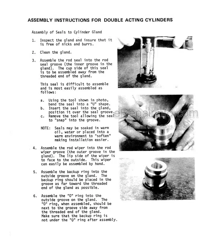
Tilt And Lift Cylinder: Sealing
Compensating And Push-Out Cylinder: Sealing
Control Cylinder (Quickhitch Frame): Sealing
Work Hydraulics Diagram
-ELECTRICAL SYSTEM
Ohm’s Law (Current, Voltage, Resistance); Power
Measuring Equipment, Measuring Methods
Terminal Description
Cable Color Coding
Relays
Fuse Box, Relays: Overview
Setting The Safe Load Indicator
Steering Electronics
Instrument Panel, Fuse Box, Relays: Overview
Wiring Diagram: Legend
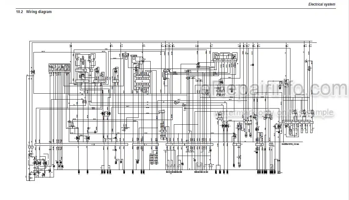
Wiring Diagram
Wiring Harness 208587 Engine – Frame 125 mph (20 km/h): Legend
Wiring Harness: 208587 Engine-Frame 125 mph (20 km/h)
Wiring Harness 208689 Engine – Frame 25 mph (40 km/h): Legend
Wiring Harness: 208689 Engine – Frame 25 mph (40 km/h)
Wiring Harness 208659 For Cab: Legend
Wiring Harness 208659 For Cab
Wiring Harness 208701 For Cab (High Speed)
Wiring Harness 208700 For Roof
Wiring Harness For Roof
Wiring Harness 208562 On Control Lever Base
Wiring Harness 207409 For Rear/Clearance Lights
Wiring Harness 1000103376 Telescopic
Wiring Harness 208111 For Additional Circuit (Optional)
Wiring Harness 208609 (Joystick)
Electronics Between Joystick And Wiring Harness 208609
Wiring Harness 208589 For Load Stabilizer
Wiring Harness 208676 For Load Stabilizer Solenoid Valve (Option)
Wiring Harness 207410 For Control Lever Lock For Long-Haul Travel
Wiring Harness 207407 For Lock For Long-Haul Travel, Instrument Panel
Wiring Harness 207411 For High Flow Additional Hydraulics (Option)
Wiring Harness 207997 For Front Socket (Option)
Wiring Harness 207999 For Safe Load Sensor
Plug And Socket Connection: Steering Electronics – Steering-Column Control Lever
Plug And Socket Connection: Fuse Box And Left-Hand Side Relays
Relay Assignment (Center)
Plug And Socket Connection: Fuse Box And Right-Hand Side Relays
Plug And Socket Connection: Cab
What you get
You will receive PDF file with high-quality manual on your email immediately after the payment.
Reviews
There are no reviews yet.