Factory Service Manual For Tigercat Mulcher. Manual Contains Illustrations, Instructions, Diagrams For Step By Step Remove And Install, Assembly And Disassembly, Service, Inspection, Repair, Troubleshooting, Tune-Ups.
Format: PDF
Language: English
Pages: 276
Number: 33591A (march 2010)
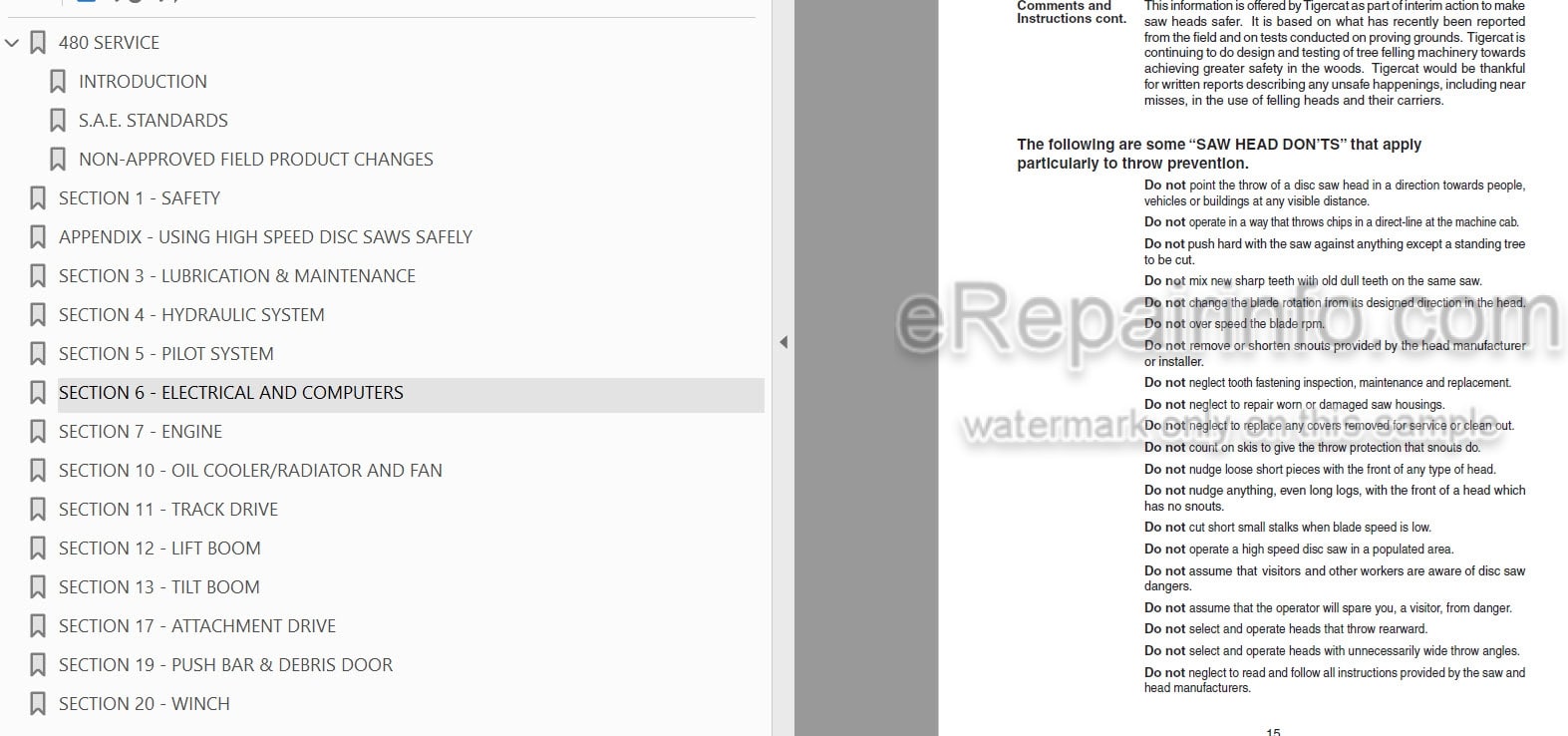
Bookmarks
Searchable
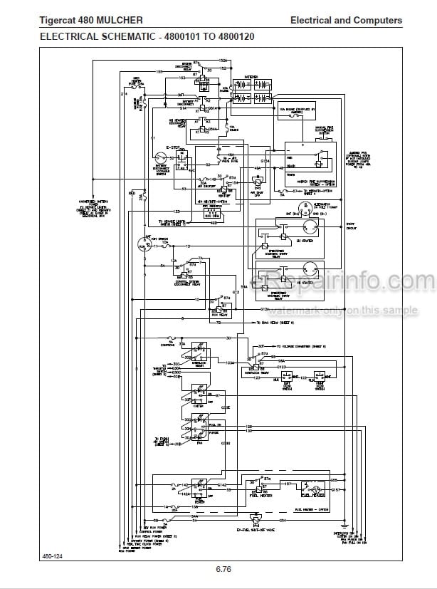
Wiring Diagrams
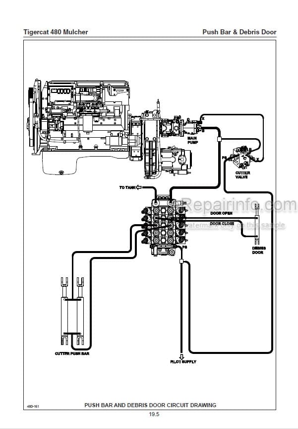
Hydraulic Diagrams
Model
Tigercat Mulcher
480
Contents
INTRODUCTION
SAE STANDARDS
NON-APPROVED FIELD PRODUCT CHANGES
-SAFETY
Battery Disconnect Switch
Boom Lift Lock
Cab Exits
Emergency Cab Exits
Fire Prevention
Fluid Injection Injury
Grease Injection Injury
Hazard Zone
Lightning Safety Awareness
Mulching Operation Safety
Parking The Machine
Safety Interlock Switches On Cab Doors
Safety Labels
Safety Precautions, General
Safety Precautions, Operating
Safety Precautions Servicing
Signal Words
-USING HIGH SPEED DISC SAWS SAFELY
Comments And Instructions
Dangers
Forward
High Angle Wrist Rotation Capability
Saw Head Donts
Type Of Housing Makes A Difference
-LUBRICATION & MAINTENANCE
Air Cleaner
Air Conditioning System, Checking
Air Filter Elements
Air Precleaner
Case Drain Strainer
Emergency Exits, Check Daily
Engine
Filters
Fire Prevention
Hydraulic Oil Return Filters
Hydraulic Oils
Lubrication And Service Points
New Machine Maintenance
Oil Lost From Leakage
Oil Sample Collection Procedures
Oil Sampling Program
Pressure Settings
Scheduled Maintenance
Service And Lubrication Points
Torque, Fluid Connections
Weights Of Commercial Wood
Winch
-HYDRAULIC SYSTEM
Filters
Hydraulic Oil Return Filters
Hydraulic System Operation
Pressure Settings
Pressure Settings Pump Control Valve
-PILOT SYSTEM
Instrument Panel
Interlock System
Interlock System Electrical
Pilot Circuit Schematic
Pilot Functions
Pilot Pressure Check
Pilot System Components
Pilot System Electronic And Hydraulic Controls
Pilot System General Description
-ELECTRICAL AND COMPUTERS
Alternator
Alternator Belt
Battery Compartment
Battery Disconnect Switch
Channels
Computer
Computer System Components And Connections
Connect To The Md3 With Iq An Run 2
Downloading Applications From Dealer Website
Drive Limiter
Electrical Kit – Service And Diagnostics
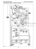
Electrical Schematic
Electrical System
Fuse And Relay Panel
Id-Tag
IQAN Modules
IQANRUN 2
IQAN Software
MD3 Computer
MD3 Computer Main Menu
Screen Saver Adjustment
Servicing The MD3 With IQANRUN 2
Troubleshooting
Update Application
-ENGINE
Charge Air Cooler
Cooling System
Engine
Start Circuit Diagram
Starting Engine
Starting System Description
-OIL COOLER/RADIATOR AND FAN
Charge Air Cooler
Cleaning
Fan
Fan Maintenance
Oil Cooler
-TRACK DRIVE
Brake Circuit Description
Circuit Diagram, Drive System
Circuit Hydraulic Schematic
Drive Motor
Drive Motor And Gearbox Assembly
Drive Motor Begin Of Stroke Adjustment
Drive Pump Charge Pressure
Drive Pump High Pressure Relief And POR Valve Adjustment
Gearbox And Drive Motor Assembly
Pump Drive Gearbox
Schematic Diagrams
Track
Track Components
Track Drive Assembly
Track Drive Circuit Diagram
Track Drive Hydraulic Schematic
-LIFT BOOM
Boom Lift Lock
Boom Valve
Circuit Diagram
Joystick Control Valve
Pressure Settings
Pump, Description
-TILT BOOM
Boom Cylinder Lock
Boom Valve
Circuit Diagram
Joystick Control Valve
Pressure Settings
Pump, Description
-ATTACHMENT DRIVE
Attachment Drive Components
Attachment Hydraulic Schematic
Attachment Motor
Attachment Pump
Circuit Description
Pressure Settings Attachment Pump And Attachment:
Safety
Set Cutter Control Valve Main Relief And Pump ’POR’
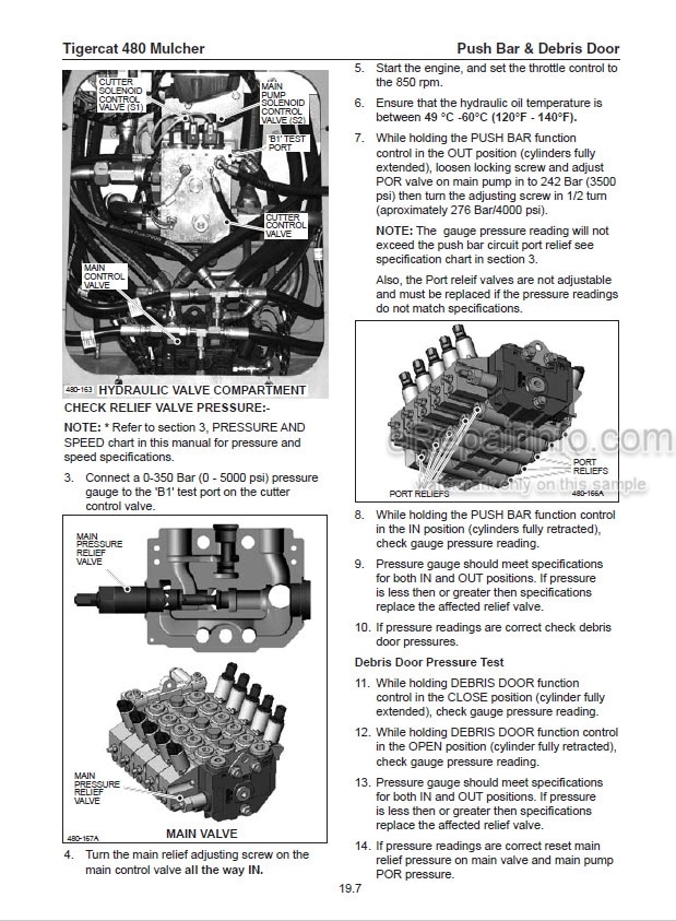
Set Motor Begin Of Displacement Control
Set Motor Minimum Displacement
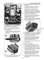
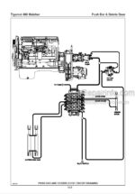
-PUSH BAR & DEBRIS DOOR
Circuit Description
Circuit Diagram
Cross Section Of Valve Spool Section
Pressure Settings
Safety
-WINCH
Circuit Description
Circuit Diagram
Cross Section Of Valve Spool Section
Pressure Settings
What you get
You will receive PDF file with high-quality manual on your email immediately after the payment.

Reviews
There are no reviews yet.