


Factory Service And Maintenance Manual For Tigercat Feller Buncher. Manual Contains Illustrations, Instructions, Diagrams For Step By Step Remove And Install, Assembly And Disassembly, Service, Inspection, Repair, Troubleshooting, Tune-Ups.
Format: PDF
Language: English
Quantity of Manuals: 2
Pages: 586; 590
Number: 44831AENG (november 2018)
Bookmarks
Searchable
Wiring Diagrams
Hydraulic Diagrams
Model
Tigercat Feller Buncher
822D
L822D
Serial Number 82213001–82214000
Serial Number 82223001–82224000
Contents
-INTRODUCTION
Machine Identification And Serial Numbers
Standards For Machine Operator Protective Structures
Non-Approved Field Product Changes
Regulatory Information
-SAFETY
Avoid Injury From Backover Accidents
Battery Disconnect Switch
Battery Safety
Boom System Precautions
Cab Exits
Cable Assist
Cooling System
Diesel Exhaust Fluid (DEF)
Engine Doors
Er Boom System
Exhaust Fumes
Felling Trees
Fire Prevention
Fluid Injection Injury
General Safety Precautions
Grease Injection Injury
Hazard Zone
Interlock Door Switche-Front
Lightening Safety Awareness
Loose Clothing Hazard
Machine Stability And Traction
Operating Safety Precautions
Parking The Machine
Protective Clothing
Safety Signal Words
Servicing Safety Precautions
Welding, Prior To
Working With Oil
-USING HIGH-SPEED DISC SAWS SAFELY APPENDIX TO SECTION 1
Comments And Instructions
Dangers
Foreword
Housing Types
Saw Head Do Nots
Type Of Housing Makes A Difference
-CONTROLS AND OPERATION
A/C/Defrost Switch
Adjustment Procedure
Adjust Menu
Aftertreatment System
Air Source Switch
Alarm
Anti-Stall, Switch With Light
Attachment, Instructions And Precautions
Audio System
Auto-Accumulate
Auxiliary Input
Auxiliary Power Outlet, 12 V
Battery Boosting
Battery Disconnect Switch
Belt, A/C Compressor
Belt Routing, Serpentine
Boom Controls
Camera
Camera Display
Clean Out Covers
Cold Weather Starting
Computer
Computer And Display
Control Panel
Control Pedals, Track Drive
Controls
Coolant Shut-Off Valves, Engine
Cooling Fan Switch
Critical Messages, Red
Current Output Channels
Default Settings Table
Diesel Exhaust Fluid (DEF)
Display, Camera
Electronic Device Holder
Emergency Exits
Engine Anti-Stall, Switch With Light
Engine Compartment Power Roof Switch
Engine Coolant Heater Controls (Optional)
Engine Coolant Shut-Off Valves
Engine Fault Code Messages
Engine Idle Speed Switch
Engine, Restarting After Engine Runs Out Of Fuel Or When A Fuel Filter Is Replaced
Engine, Stopping
Er Boom System, Instructions
Fan Speed Switch
Filters
Fire Extinguisher, Cab
Fire Extinguisher, Portable
Fire Suppression System (Optional)
Fire Suppression System, Using
Fuel Heater
Fuel, Refuelling
Fuel Tank
Heat/Cool Temperature Knob
Heater Controls, Engine Coolant (Optional)
Horn/Safety Alert Switch
Hydraulic Adjustments Table
Info Menu
Information Messages, Blue
Inspection Of The Fire Suppression System And Portable Extinguishers
Interior Cab Light Switch
Joystick Controls, Buttons And Trigger
Joystick Controls, Lever
Key Switch
Lights
Load Sensing, Operating Tips
Machine Parameters
Machine Preparation
Operating Machine
Operating Tips With Load Sensing
Operator’s Manual Case
Operator’S Seat (822*3422 To 822‘4000)
Operator’s Seat–Air Ride (822*3001–822*3421)
Pictograms
Pilot Interlock Door Switch
Pilot System Off, Push Button Switch
Pilot System Reset Switch
Refuelling
Restarting An Engine
Saw Switch
Screen, Side Window
Serpentine Belt Routing
Service Work Light Switch And Indicator Light
Slope Indicators
Starting Engine
Swing Brake Switch
Swing Control, Joystick
Switch
Timed Purge Interval
Track Drive, Control Pedals
Track Drive Switch
Travelling, Boom Raised
Travel Speed Control
USB Connection
Warmup Mode
Work Light Switches
-LUBRICATION AND MAINTENANCE
Access Doors And Covers
Access Door Undercarriage, Swivel
Aftertreatment System
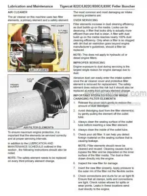
Air Cleaner
Air Conditioning System
Air Filters
Air Intake System
Anti-Corrosion Spray, Removal, If Applicable
Approved Anti-Seize Pastes For Exhaust/Aftertreatment Sensors
Battery Care
Care Of Polycarbonate Windows
Care Of The Machine
Case Drain Strainers
Checking The Air Conditioning System
Cleaning
Cleaning Cooler Package
Clean Out Cover
Commercial Wood-Weights
Cooler Package-Cleaning
Diagnostics Connection, Engine
Diesel Exhaust Fluid (DEF)
Diffusers
Diffusers/Strainers-Hydraulic Oil Return
Dozer Blade Attachment (Optional) Lubrication Points
Emergency Exits
Emergency Exits, Check Monthly
Engine Diagnostics Connection
Erboom System
Escape Hatch Replacement
Filters
Fire Prevention
Fire Suppression System (Optional)
Fuel, Bottom Refuelling Procedure
Fuel Cooler
Fuel, Refuelling Procedure
Fuel System
Fuel Tank
Fuses And Relays
Graffiti Removal
Hydraulic Oil Fill Pump
Hydraulic Oil Level Sight Guides
Hydraulic System
Leveler Component Lubrication Points 822*3001-822*3421
Leveler Component Lubrication Points 822*3422-822*4000
Leveler Cylinder Locks
Machine Parameters
New Machine Maintenance
Oil Analysis Program
Oil Lost From Leakage
Oil Sampling Program
Power Roof And Side Door, Engine
Pressure And Speed Settings 822*3001 To 822*3502
Pressure And Speed Settings 822*3503 To 822*4000
Pressure Washing
Preventive Maintenance Schedule
Pump Compartment Access Doors
Pump Hand, Hydraulic, Engine Compartment Roof And Side Door
Refilling The Hydraulic System
Refuelling Procedure
Relays And Fuses
Rotary Manifold Seal, Lubrication
Scheduled Maintenance
Serpentine Belt Routing
Service/Access Doors And Covers
Service And Lubrication Schedule 822*3001 -822*3142
Service And Lubrication Schedule, 822*3143 – 822*3250
Service And Lubrication Schedule, 822*3251 -822*4000
Startup Procedure After Major Machine Maintenance
Strainers, Case Drain
Swing Drive Lubrication
Timed Purge Interval
Torque Chart, General
Torque Chart, Machine
Torque, Fluid Connections
Track
Track Drive Gearbox
Track Operation And Wear Prevention
Weights Of Commercial Wood
Windows
Wood, Weights Of Commercial Wood
-HYDRAULIC SYSTEM
Case Drain Strainers
Diffusers/Strainers-Hydraulic Oil Return
Filters
Filters, Hydraulic Oil
High Pressure Limiting Control Valve
Hydraulic Oil Tank
Hydraulic Pumps
Hydraulic System Operation
Load Sensing
Main Control Valve/Manifold
Schematic Diagrams
Strainers, Case Drain
-PILOT SYSTEM
Accumulator
Electrical Circuit-Pilot System
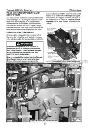
Pilot System Components
Pilot System Electrical Circuit Diagram
Pilot System Schematic
-ELECTRICAL AND COMPUTERS
Battery Booster Jumper Plug
Cab Electrical Panel
Channels
Computer
Computer Modules
Connect To The Computer With Iqanrun 4
Downloading Applications From Dealer Website
Electrical Installation-Cab
Electrical Kit-Service And Diagnostics
Electrical Panel-Cab
Electrical Schematics
Fuses And Relays
Id-Tag
Iqanrun 4
Iqan Software
Relays And Fuses
Servicing The Computer With Iqanrun 4
Switch And Sensor Locations
Wire Colour Code Chart
-ENGINE AND ANTI-STALL
Anti-Stall
Cold Weather Starting
Computer
Electrical Schematics
Flex Drive Coupling Installation
Machine Preparation
Restarting An Engine That Has Run Out Of Fuel Or When A Fuel Filter Has Been Replaced
Schematic Diagrams
Starting Engine
Stopping Engine
-COOLING SYSTEM
Charge Air Cooler
Circuit Description
Computer
Fan Circuit Hydraulic Schematic
Fan Drive Control Valve
Fan Drive Electrical Schematic
Fan Pump
Fan Pump/(Max) Maximum Pressure
Fan Speed Checks
Filters
Hydraulic Oil Tank
Oil Cooler
Radiator
-TRACK DRIVE
Begin Of Regulation
Circuit Diagram, Drive System
Drive Motor
Hydrostatic Drive System
Important Track Drive Notes
Left Track Speed Adjustment
Pressure Settings
Rotary Manifold
Rotary Manifold Seal Installation
Schematic Diagrams
Set Straight Travel
Track
Track Components
Track Drive Assembly
Track Speed Set-Up Procedure
-BOOM FUNCTIONS
Adjust Oil Flow To Cylinders
Er Boom Operation
Er Boom System Circuit Diagram
Er Boom System-Service Position
Er Boom System-Service Safety
Er Boom Valve Connections
Main Control Valve
Port Reliefs
Pressure Gauge Connections
Pressure Settings, Port Relief Valves
Typical Cylinder Cycle Times
-LEVELING
Check Leveling Control Valve Port Relief Pressure
Check Leveling Speed
Hydraulic Circuit Diagram Leveling System Undercarriage Components
Hydraulic Circuit Diagram Leveling System Upper Structure Components
Hydraulic Schematic, Counterbalance Valve
Hydraulic Schematic, Leveling Control Valve, Counterbalance Valves, And Leveling Cylinders
Leveler Component Lubrication
Leveling Circuit Description
Leveling Control Valve
Leveling Cylinder Counterbalance Valves
Leveling Cylinder Tapered Lock Pins
Leveling Electronic Adjustment
Side Pivot Axis Bearings
-DOZER BLADE
Dozer Blade Attachment (Optional)
Hydraulic Circuit Diagram Dozer Blade
Hydraulic Schematic, Counterbalance Valve (Dozer Blade Cylinders)
Hydraulic Schematic, Diverter Valve (Left Or Right)
Hydraulic Schematic, Dozer Blade
Lubrication Points, Dozer Blade Attachment
Pressure Setting, Dozer Blade Cylinder Counterbalance Valve
-SWING
Adjust Oil Flow To Swing Motor (Swing Motor Speed)
Circuit Description
Circuit Diagram
Crossline Relief Valves
Pressure Settings
Rotary Manifold Seal-Lubrication
Schematic Diagrams
Set Swing Motor Speed
Swing Bearing
Swing Bearing Replacement
Swing Drive Gearbox
Swing Drive Lubrication
Swing Drive Valve Priority Circuit Description
Swing System Hydraulic Schematic
-SAW DRIVE
Circuit Diagram
Circuit Hydraulic Schematic
Pressure Settings
Saw Circuit Description
Saw Control Valve
Saw Pump
-WRIST AND CLAMPS
Attachment Control Valve
Attachment Pump
Attachment Valve Adjustments
Circuit Description
Circuit Diagram
Circuit Hydraulic Schematic
Computer
Inlet Section
Pressure Checking
Replacing
What you get
You will receive PDF file with high-quality manual on your email immediately after the payment.


Reviews
There are no reviews yet