Factory Service Manual For JLG Telehandler. Manual Contains Illustrations, Instructions, Diagrams For Step By Step Remove And Install, Assembly And Disassembly, Service, Inspection, Repair, Troubleshooting, Tune-Ups.
Format: PDF
Language: English
Pages: 636; 636
Issue: february 2005
Bookmarks: Yes
Searchable: Yes
Wiring Diagrams: Yes
Hydraulic Diagrams: Yes
Model
JLG Telehandler
644B
6K
844C
8K
1044C
10K
Lull
Contents
-SAFETY
General
Maintenance Safety
Decals and Placards
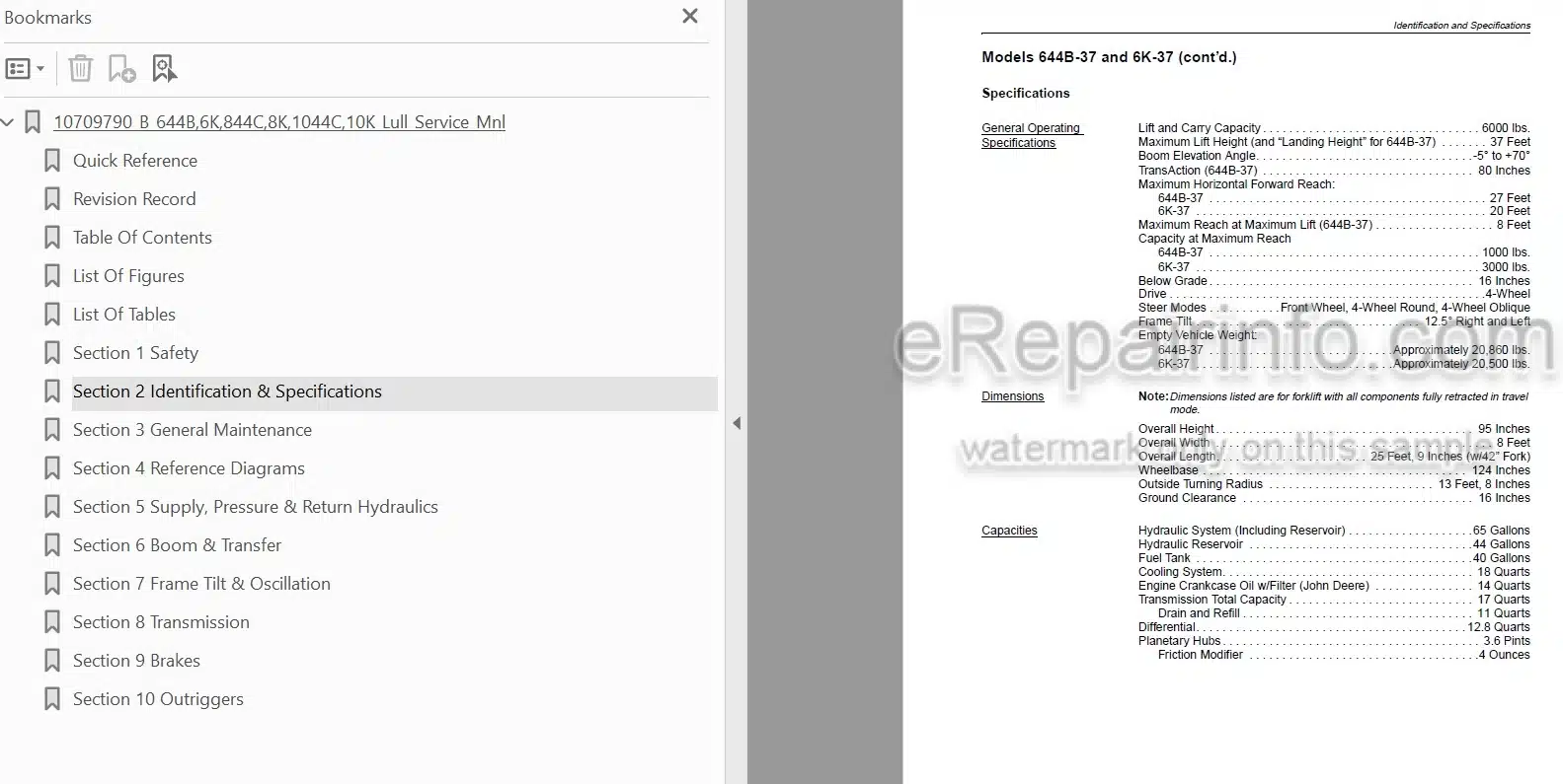
-IDENTIFICATION & SPECIFICATIONS
Serial Number Locations
Models 644B-37 and 6K-37
Models 644B-42 and 6K-42
Models 844C-42 and 8K-42
Models 1044C-42 and 10K-42
Models 1044C-54 and 10K-54
Engine Specifications
-GENERAL MAINTENANCE
General Instructions
Service Preparation Procedures
Service And Repair Procedures
Replacement Parts
Lubrication
Fluid and Lubricant Specifications
Care and Cleaning
Storage
Torque Specifications
Jump Starting Procedures
Conversion Charts
-REFERENCE DIAGRAMS
Schematic, Model 644B w/ Naturally Aspirated Engine, Control Manifold Hydraulic System
Schematic, Model 644B w/ Naturally Aspirated Engine, Mid-Inlet Hydraulic System
Pump Unloader Valve Operation, Mid-Inlet Hydraulic System
Schematic, Models 644B, 844C, 1044C-42 w/ Turbocharged Engine, Mid-Inlet Hydraulic Sys
Schematic, Model 1044C-54, Mid-Inlet Hydraulic System
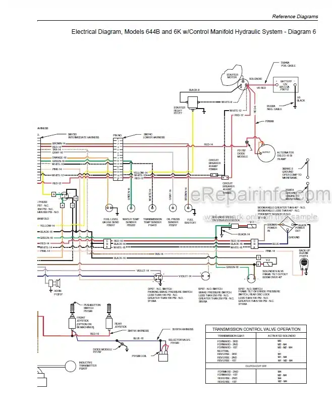
Electrical Diagram, Models 644B and 6K w/ Control Manifold Hydraulic System
Rear Oscillation Lock System Operation, Control Manifold Hydraulic System
Boom/Transfer Extend Lockout Circuit Operation, Control Manifold Hydraulic System
Rear Oscillation Lock System Operation, Mid-Inlet Hydraulic System
Rear Axle Stabilizer Control Valve Operation, Mid-Inlet Hydraulic System
Boom/Transfer Extend Lockout Circuit Operation, Mid-Inlet Hydraulic System
Electrical Diagram, ZF DW-2/EST-19 System Harness
Electrical Diagram, ZF DW-3 System Harness
-SUPPLY, PRESSURE & RETURN HYDRAULICS
General
General Hydraulic Maintenance Practices
Hydraulic Reservoir
Sight Gauge
Suction Strainer
Hydraulic Return Filter
Reservoir Breather
Hydraulic Pressure Filter
Hydraulic Pump
Multi-Spool Control Valve
Hydraulic Control Manifold
Pump Unloader Valve
Mid-Inlet Control Valve
Rear Axle Stabilizer Control Valve
Boom Extend Lockout Valve
Hydraulic Diagnostic Ports
Roll-Back Hose Tray
-BOOM & TRANSFER
Boom and Transfer Hydraulics
Joystick Controls
Hydraulic Cylinders
Boom Hoist Cylinder
Front Carriage Tilt Cylinder
Rear Carriage Tilt Cylinder
Boom Hydraulic Control Valve (Control Manifold System)
Selector Valve (Control Manifold System)
Selector Valve (Mid-Inlet System)
Troubleshooting
Boom Slide Pads — General
Quick Attach
Boom Angle Inclinometer
2-Section Boom
3-Section Boom
4-Section Boom
Boom Extension Proximity Switch
Transfer Carriage
Boom Cradle
Transfer Cylinder
-FRAME TILT & OSCILLATION
Frame Tilt System
Frame Tilt Control Valve
Frame Tilt Cylinder
Frame Level Indicator
Rear Oscillation Lock System
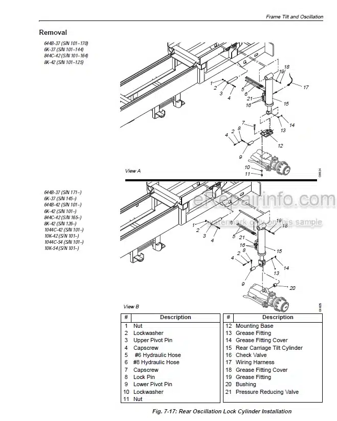
Rear Oscillation Lock Cylinder
Oscillation Control Block
Frame Tilt Lockout Valve
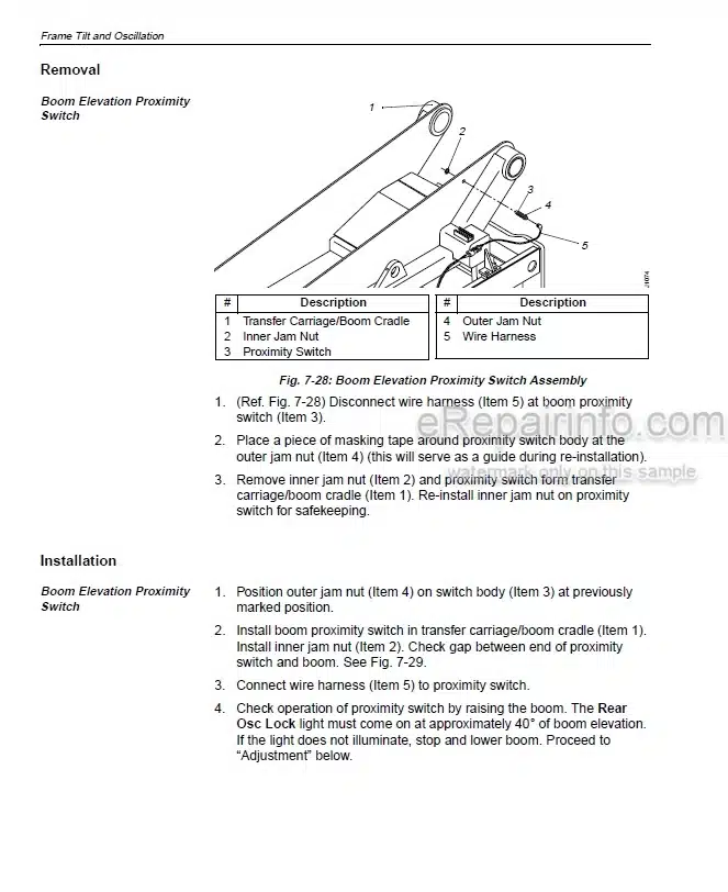
Boom Elevation Proximity Switch
-TRANSMISSION
Description
Troubleshooting and Test Procedures
-BRAKES
Service Brakes
Service Brake Pedal and Valve
Accumulator
Park Brake
-OUTRIGGERS
Outriggers
Outrigger Cylinders
Differential Pressure Switch
Boom Extension Proximity Switch
Outrigger Control Valves
What you get
You will receive PDF file with high-quality manual on your email immediately after the payment.
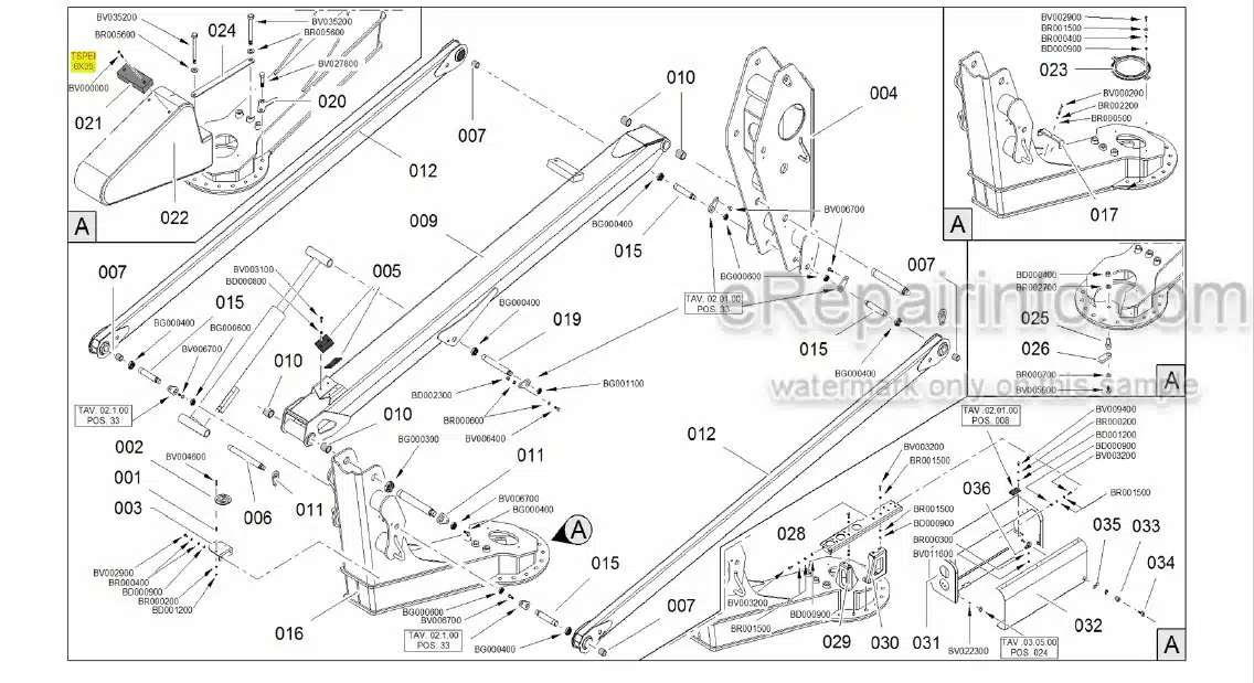
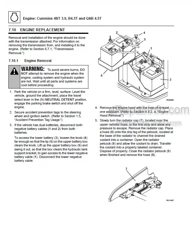
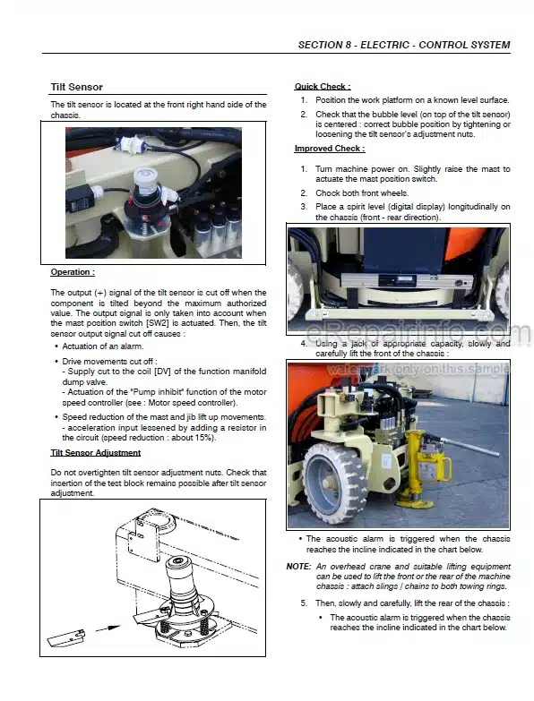
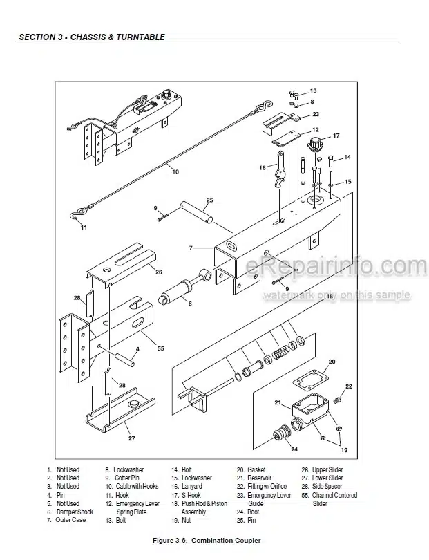
Reviews
There are no reviews yet.