


Factory Service Repair Manuals For Hitachi ZX110-3 Class, 120-3 Class, 135U-3 Class Excavators. Tons of illustrations, instructions, diagrams for step by step remove and install, assembly and disassembly, service, inspection, repair, troubleshooting, tune-ups.
Format: PDF
Language: English
Pages: 1552
Bookmarks: Yes
Searchable: Yes
Wiring Diagrams: Yes
Hydraulic Diagrams: Yes
Model
Hitachi ZX 110-3, 110M-3, 120-3, 130K-3, 130L-3, 135US-3, 135USK-3, 135USL-3
Contents
1.Technical Manual(Operational Principle)
2.Technical Manual(Troubleshooting)
3.Workshop Manual
1.Technical Manual(Operational Principle)
INTRODUCTION
-GENERAL
–SPECIFICATIONS
Specifications
Working Ranges (Grouser Shoe)
–COMPONENT LAYOUT
Main Components
Electrical System (Overview)
Electrical System (In Cab)
Electrical System (Rear Tray)
Electrical System (Switch Panel)
Electrical System (Relays)
Engine
Pump Device
Swing Device
Signal Control Valve
Control Valve
2-Spool Solenoid Valve Unit
Travel Device
Blade Control Valve (Optional)
–COMPONENT SPECIFICATIONS
Engine
Engine Accessories
Hydraulic Component
Electrical Component
2.Technical Manual(Troubleshooting)
INTRODUCTION
SAFETY
-OPERATIONAL PERFORMANCE TEST
–INTRODUCTION
Operational Performance Tests
Preparation for Performance Tests
–STANDARD
ZX110-3 Class Operational Performance Standard Table
ZX120-3 Class Operational Performance Standard Table
ZX135US-3 Class Operational Performance Standard Table
Main Pump P-Q Diagram
Sensor Activating Range
ZX110-3 Class Dr ZX Monitor Indicating Values
ZX120-3 Class Dr ZX Monitor Indicating Values
ZX135US-3 Class Dr ZX Monitor Indicating Values
–ENGINE TEST
Enyine Speed
Engine Compression Pressure
Valve Clearance
Lubricant Consumption
–EXCAVATOR TEST
Travel Speed
Track Revolution Speed
Mistrack Check
Travel Parking Leakage
Swing Speed
Swing Function Drift Check
Swing Motor Leakage
Maximum Swingable Slant Angle
Swing Bearing Play
Hydraulic Cylinder Cycle Time
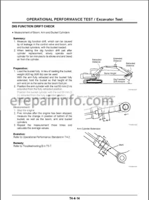
Dig Function Drift Check
Control Lever Operating Force
Control Lever Stroke
Combined Operation of Boom Raise I Swing Function Check
Combined Operation of Boom Raise / Arm Roll-In Function Check
–COMPONENT TEST
Primary Pilot Pressure
Secondary Pilot Pressure
Solenoid Valve Set Pressure
Main Pump Delivery Pressure
Main Relief Set Pressure
Relief Pressure (When Relieving Swing)
Relief Pressure (When Relieving Travel)
Overload Relief Valve Set Pressure
Mam Pump Flow Rate Measurement Swing Motor Drainage
Travel Motor Drainage
–ADJUSTMENT
Adjustment
Attachment Setting
-TROUBLESHOOTING
–DIAGNOSING PROCEDURE
Introduction
Diagnosing Procedure
–MONITOR UNIT
Outline
Howto Use Screens
Primary Screen
Screen Display
When an Alarm is Issued
Contents of Alarms
Troubleshooting
Controller Version
Monitoring
Displaying Operating Conditions
Pump 2 Flow Rate Adjustment (Only Machines Equipped
with Optional Parts)
Attachment Selection (Only Machines Equipped with Optional Parts)
Time Set
Fuel Rate Display/No Display
Back Monitor Settings
Maintenance Settings
Language Settings
Mail (Optional)
List of Monitor Unit Setting Function
–DR ZX
Outline
Select Controller
Main Controller
Main Menu Monitor Display
Special Function
Setting
Adjustment Data List
Attachment Adjustment Data List
Attachment Setting
Engine Controller
Main Menu Monitor Display
Special Function Data Upload from ECM
Data Download to ECM
Write Injection ID Code
ECM Data Display
Actuator Test
Example of Engine Speed Down & Stop Cylinder Function (on a Four-Cylinder Engine)
Record Data Display
Password Change
ICF Controller
Main Menu
Information C/U Various Setup Information C/U: Initialize
Enter Model and Serial No
Enter Date and Time
Control Data: Initialize
Satellite Terminal Initialize
Satellite Terminal Serial No Confirmation
Communicating State Check
Satellite Comm Start / Stop Set
Satellite Comm Transmitting
Date Download
Save Data Check
Password Change
Monitor Controller
Monitoring
Various Settings
Optional Function Allocation
Overload Alarm Enable / Disable Selection
Back Monitor Setting
Operating Condition Enable / Disable Selection
Time Setting Function Enable / Disable Selection
Maintenance Setting Maintenance Operation Allow / Not Allow Selection
Notification Function Enable / Disable Selection
Maintenance Display Item On/Off Selection
Fuel Consumption Gauge Display Enable / Disable Selection
Password Change
–E-SHOVEL
Outline
List of Daily Report Data
List of Frequency Distnbution Data List of Total Operating Hours
How to Download and Upload Data of ICF
Various Setup of ICF and Satellite Communication Terminal by Using Dr ZX
List of Fault Code
Satellite Communication System
–COMPONENT LAYOUT
Mam Components
Electrical System (Overview)
Electrical System (In Cab)
Electrical System (Rear Tray)
Electrical System (Switch Panel)
Electrical System (Relays)
Engine
Pump Device
Swing Device
Control Valve
Signal Control Valve
2-Spool Solenoid Valve Unit
Travel Device
Blade Control Valve (Optional)
–TROUBLESHOOTING A
Troubleshooting A Procedure
Fault Code List MC
ECM
ICF
Controller Hardware Failure
MC Fault Code 11000 to 11002
MC Fault Code 11003
MC Fault Code 11004
CAN Harness Check
Engine Failure
MC Fault Code 11100
MC Fault Code 11101
Pump Failure
MC Fault Code 11200
MC Fault Code 11202
MC Fault Code 11206
MC Fault Code 11208
Pilot Failure
MC Fault Code 11301
MC Fault Code 11302
MC Fault Code 11303
MC Fault Code 11304
MC Fault Code 11307
Proportional Solenoid Valve Failure
MC Fault Code 11400
MC Fault Code 11401
MC Fault Code 11403
MC Fault Code 11405
CAN Data Reception Failure
MC Fault Codes 11910,11914 11920
CAN Harness Check
MC Fault Codes 11910,11914, 11920
MC Fault Codes 11911,11918
CAN Harness Check
Fault Codes 11911, 11918
Other Failures
MC Fault Code 11901
ECM, Sensor System
ECM Fault Codes 100, 102, 105, 108, 110, 157, 172
ECM Fault Codes
174, 636,723, 10001
ECM, External Device System
ECM Fault Codes 651, 652, 653, 654,655656,1347,10002 ‘
ECM, Fuel System
ECM Fault Codes
157, 633,1239, 1240
ECM, Engine Protection
ECM Fault Codes 110, 190
ECM, Engine Protection
ECM Fault Codes 987, 1485
ECM, Internal Circuit System
ECM Fault Codes 628,1077, 1079,
1080, 10003, 10004, 10005
ECM Fault Codes 10006, 10007, 10008, 10009, 10010, 10011, 10013
ECM, Communication System ECM Fault Codes 639
ICF Satellite Terminal Fault Codes 14000 to 14003
ICF, Satellite Terminal Fault Codes 14006 14008, 14100 to 14106T
Monitor Unit Fault Code 13303
Monitor Unit Fault Code 13304
Monitor Unit Fault Code 13306 1 3308
Monitor Unit Fault Code 13310
Monitor Unit Fault Code 13311
Pilot Shut-Off Lever Alarm
–TROUBLESHOOTING B
Troubleshooting B Procedure
Relationship between Machine Trouble Symptoms and Related Parts
Correlation between Trouble Symptoms and Part Failures
Engine System Troubleshooting
All Actuator System Troubleshooting
Front Attachment System Troubleshooting
Swing System Troubleshooting
Travel System Troubleshooting
Other System Troubleshooting
Exchange Inspection
Emergency Boom Lowering Procedure
Circuit Pressure Release Procedure
One Part of Data ’Daily Report Data”
“Distribution Data’ and ‘Total Operating hours’ is not Recorded
–ELECTRICAL SYSTEM INSPECTION
Precautions for Inspection and Maintenance
Instructions for Disconnecting Connectors
Fuse Inspection
Fusible Link Inspection
Battery Voltage Check
Alternator Check
Continuity Check
Voltage and Current Measurement
Check by False Signal
Test Harness
3.Workshop Manual
INTRODUCTION
SAFETY
-GENERAL
–PRECAUTIONS FOR DISASSEMBLING AND ASSEMBLING
Precautions for Disassembling and Assembling
Maintenance Standard Terminology
–TIGHTENING
Tightening Torque Specifications
Torque Chart
Piping Joint
Periodic Replacement of Parts
–PAINTING
Painting
–BLEEDING AIR FROM HYDRAULIC OIL TANK
Bleeding Air from Hydraulic Oil Tank
-UPPERSTRUCTURE
–CAB
Removal and Installation of Cab (ZX110-3 class, 120-3 class)
Removal and Installation of Cab (ZX135US-3 class)
Dimensions of Cab Glass (ZX110-3 class, 120-3 class)
Dimensions of Cab Glass (ZX135US-3 class)
–COUNTERWEIGHT
Removal and Installation of Counterweight (ZX110-3 Class, 120-3 Class)
Removal and Installation of Counterweight (ZX135US-3 Class)
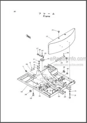
–MAIN FRAME
Removal and Installation of Main Frame
–PUMP DEVICE
Removal and Installation of Pump Device (ZX110-3 class, 120-3 class)
Removal and Installation of Pump Device (ZX135US-3 class)
Disassembly of Main Pump
Assembly of Main Pump
Disassembly of Regulator
Assembly of Regulator
Disassembly of Solenoid Valve
Assembly of Solenoid Valve
Disassembly and Assembly of Gear Pump
Disassembly and Assembly of Gear Pump (Optional)
Maintenance Standard
–CONTROL VALVE
Removal and Installation of Control Valve (ZX110-3 class, 120-3 class)
Removal and Installation of Control Valve (ZX135US-3 class)
Disassembly of Control Valve 4-Spool Side
Disassembly of Control Valve 5-Spool Side
Assembly and Disassembly of 4-Spool Side and 5-Spool Side
Assembly of Control Valve 4-Spool Side
Assembly of Control Valve 5-Spool Side
Disassembly of Blade Control Valve (Optional)
Assemble of Blade Control Valve (Optional)
–SWING DEVICE
Removal and Installation of Swing Device (ZX110-3 class 120-3 class)
Removal and Installation of Swing Device (ZX135US-3 class)
Disassembly of Swing Device
Assembly of Swing Device
Disassembly of Swing Motor
Assembly of Swing Motor
Disassembly of Valve Unit
Assembly of Valve Unit
Maintenance Standard
–PILOT VALVE
Removal and Installation of Pilot Valve
Disassembly of Right and Left Pilot Valves
Assembly of Right and Left Pilot Valves
Disassembly of Travel Pilot Valve
Assembly of Travel Pilot Valve
–PILOT SHUT-OFF SOLENOID VALVE
Removal and Installation of Pilot Shut-Off Solenoid Valve
Disassembly of Pilot Shut-Off Solenoid Valve
Assembly of Pilot Shut-Off Solenoid Valve
–SIGNAL CONTROL VALVE
Removal and Installation of Signal Control Valve (ZX110-3 class 120-3 class)
Removal and Installation of Signal Control Valve (ZX135US-3 class)
Structure of Signal Control Valve
–2-SPOOL SOLENOID VALVE UNIT
Removal and Installation of 2-Spool Solenoid Valve Unit (ZX110-3 class, 120-3 class)
Removal and Installation of 2-Spcol Solenoid Valve Unit (ZX135US-3 class)
Structure of 2-Spool Solenoid Valve Unit
–ENGINE
Removal and Installation of Engine (ZX110-3 class, 120-3 class)
Removal and Installation of Engine (ZX135US-3 class)
-UNDERCARRIAGE
–SWING BEARING
Removal and Installation of Swing Bearing
Disassembly of Swing Bearing
Assembly of Swing Bearing
–TRAVEL DEVICE
Removal and Installation of Travel Device
Disassembly of Travel Device
Assembly of Travel Device
Disassembly of Travel Motor
Assembly of Travel Motor
Disassembly of Brake Valve
Assembly of Brake Valve
Maintenance Standard
–CENTER JOINT
Removal and Installation of Center Joint
Disassembly of Center Joint
Assembly of Center Joint
Maintenance Standard
–TRACK ADJUSTER
Removal and Installation of Track Adjuster
Disassembly of Track Adjuster
Assembly of Track Adjuster
–FRONT IDLER
Removal and Installation of Front Idler
Disassembly of Front Idler
Assembly of Front Idler
Maintenance Standard
–UPPER AND LOWER ROLLER
Removal and installation of Upper Roller
Removal and Installation of Lower Roller
Disassembly of Lower Roller
Assembly of Lower Roller
Maintenance Standard
–TRACK
Removal and Installation of Track
Maintenance Standard
-FRONT ATTACHMENT
–FRONT ATTACHMENT
Hydraulic Circuit Pressure
Release Procedure
Removal and Installation of Front Attachment (Monoblock Boom)
Maintenance Standard
Standard Dimensions for Arm and Bucket Connection
Standard Dimensions for Arm and Boom Connection
–CYLINDER
Hydraulic Circuit Pressure Release Procedure
Removal and Installation of Cylinder Disassembly of Boom and Bucket Cylinders
Disassembly of Arm Cylinder
Assembly of Boom and Bucket Cylinders
Assembly of Arm Cylinder
Maintenance Standard
What you get
You will receive PDF file with high-quality manual on your email immediately after the payment.


Reviews
There are no reviews yet.